Work on "SparkDD" status

Chevy Spark EV Forum

Help Support Chevy Spark EV Forum:

This site may earn a commission from merchant affiliate links, including eBay, Amazon, and others.

solder

Well-known member
Joined
Jan 10, 2015
Messages
93
Location
2015 Spark EV, NorCal
I've touched on this on a number of threads here, but starting a new thread for visibility.

One of the members of the Leaf community has come out with a really slick plug-in device that can display detailed battery stats: http://www.mynissanleaf.com/viewtopic.php?f=44&t=12561

Without ripping off his idea, I'd like to see what we can do for the Spark EV (and possibly the Volt?) and I've been making slow progress towards that end:
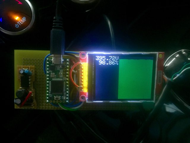


What you're looking at is the raw battery pack voltage for the car, as well as the system's computed percentage SoC, and then the individual battery voltages for each of the 96 cells banks in my car. (112 cells banks in 2014). I have more information available that I am not displaying; see http://www.mychevysparkev.com/forum/viewtopic.php?p=10016#p10016

I'm not happy with the fit and finish of the display, nor am I happy with the clarity of the display. I'd welcome feedback as to a better way to make use of the 320x240 color display that I am using.

I have a PCB in the mail that will clean up this design significantly, adding a switching 12v->5v regulator, push button (to select modes, if we so desire), and some SWCAN circuitry to prototype the reverse-camera support:
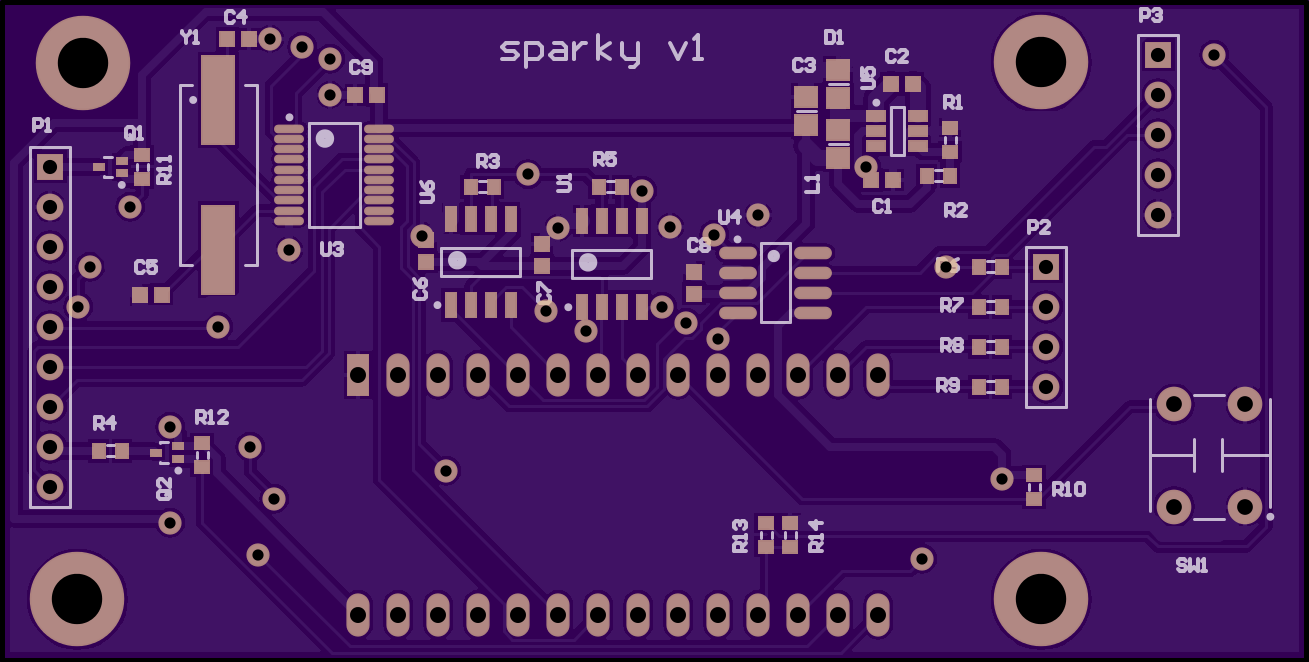


I have somewhat different plans for this than the LeafDD. The LeafDD is a polished, semi-commercial product without user-upgradeable firmware. My device uses the Teensy 3.1 and can be updated with the Arduino IDE (plus TeensyDuino plugin); I plan on releasing full source on github (in the hopes that others will help me tweak it). Unless I have a change of heart, I will be making the plans available for free, selling bare PCBs for cheap, and hand-assembling units for those who can't solder SMD parts. (I just really don't think there are enough of us to justify making a business out of this.)

For those curious, the parts on board are:
* 12v->5v switching supply
* Teensy3.1
* 320x240 SPI LCD with optional SD card interface
* High-speed CAN interface
* External CAN controller to add a second CAN channel
* SWCAN interface circuitry for rear-camera prototyping

I'm trying to do this using low-cost parts... hopefully it will work out and serve as a platform for further experimentation.

I'll update this thread as things progress; currently have all the parts but am waiting on the PCBs.
 
solder said:
I've touched on this on a number of threads here, but starting a new thread for visibility.

One of the members of the Leaf community has come out with a really slick plug-in device that can display detailed battery stats: http://www.mynissanleaf.com/viewtopic.php?f=44&t=12561

Without ripping off his idea, I'd like to see what we can do for the Spark EV (and possibly the Volt?) and I've been making slow progress towards that end:


What you're looking at is the raw battery pack voltage for the car, as well as the system's computed percentage SoC, and then the individual battery voltages for each of the 96 cells banks in my car. (112 cells banks in 2014). I have more information available that I am not displaying; see http://www.mychevysparkev.com/forum/viewtopic.php?p=10016#p10016

I'm not happy with the fit and finish of the display, nor am I happy with the clarity of the display. I'd welcome feedback as to a better way to make use of the 320x240 color display that I am using.

I have a PCB in the mail that will clean up this design significantly, adding a switching 12v->5v regulator, push button (to select modes, if we so desire), and some SWCAN circuitry to prototype the reverse-camera support:


I have somewhat different plans for this than the LeafDD. The LeafDD is a polished, semi-commercial product without user-upgradeable firmware. My device uses the Teensy 3.1 and can be updated with the Arduino IDE (plus TeensyDuino plugin); I plan on releasing full source on github (in the hopes that others will help me tweak it). Unless I have a change of heart, I will be making the plans available for free, selling bare PCBs for cheap, and hand-assembling units for those who can't solder SMD parts. (I just really don't think there are enough of us to justify making a business out of this.)

For those curious, the parts on board are:
* 12v->5v switching supply
* Teensy3.1
* 320x240 SPI LCD with optional SD card interface
* High-speed CAN interface
* External CAN controller to add a second CAN channel
* SWCAN interface circuitry for rear-camera prototyping

I'm trying to do this using low-cost parts... hopefully it will work out and serve as a platform for further experimentation.

I'll update this thread as things progress; currently have all the parts but am waiting on the PCBs.
Solder,

Very cool project!!! Please let me know when the PCB (fully populated or bare board available - if bare board, can you provide the BOM?).
What enclosure do you have for the board? How does the cable connect to Spark's CAN bus?
 
I'm also really interested in this! Keep us updated and informed, especially if you are planning on selling this to other techies!

I'm particularly interested in the balancing on the individual modules on my vehicle as well. The other thing to note is that the pack configuration between the 2014 and 2015 Spark is different so graphing the cell voltages might require some detection of the model years. Which Spark Model do you have?
 
Cool project. I'm not great with electronics or software, but I'm pretty good with CAD. Perhaps I can help model up a housing that could be 3D printed when you've got a fixed PCB/screen setup determined.

Food for thought. Since you're on CAN already, you could use one of the buttons that are already on the car as an input and skip your own button. For example, the "Sport" button doesn't really do anything, you could just watch for state change on that signal and use that for mode selection. For example, a single state change within 5 seconds is ignored, but if state changes 2+ times in 5 seconds then it would be treated as a signal to change the display mode.

I'm pretty sure I sniffed the Sport mode out in the CAN already, I might be able to provide the CAN ID if you're interested in shifting away from hardware to software for that. Might make the real estate claim shrink a bit.

Bryce
 
Again nice work solder,

As Nashco wrote, you may use car Buttons to make it look more OEM.
I can provide you with all desired buttons. I for myself use the steeringwheel buttons for switching views.


Bernd
 
Very cool!

Are you sure you want to go do this route though?

Turbo3 on MNL (I've met twice and he lives a few miles from me) created WattsLeft (more info at http://www.mynissanleaf.com/viewtopic.php?f=44&t=8527 and http://www.mynissanleaf.com/viewtopic.php?f=44&t=8527&start=120 ). He had to program that microcontroller chip he had all in assembly language and it has very limited EEPROM storage and RAM.

Per his OP "The SX28AC is a very basic single chip system with 2K words (12 bits) of EEPROM program storage, 136 bytes of RAM all inside a 28 pin package with 20 general purpose I/O pins. The instruction set is similar to the PIC16C5x series but with a few more instructions. It can run at up to 75 MHz with one instruction executed each cycle (except for jumps/calls, of course)."

His device plugged into the OBD2 port on the Leaf.

The times I met him (years ago, shortly before and after TonyWilliams Phoenix Leaf range test: http://www.mynissanleaf.com/viewtopic.php?p=228326), the above was still an active project.

I believe he's abandoned that and instead moved onto both an app for Android and more recently, iOS. (Have not talked to him since these started up.)
Android:
http://www.mynissanleaf.com/viewtopic.php?f=44&t=14284
http://www.mynissanleaf.com/viewtopic.php?f=44&t=14285
http://www.electricvehiclewiki.com/?title=Leaf_Battery_Application

iOS: http://www.mynissanleaf.com/viewtopic.php?f=44&t=18917

I'd imagine it gives him freedom to do WAY more and w/o being so limited on the hardware side w/o also needing to program in assembly language (eek).

I'd imagine he also probably is more profitable/efficient selling paid versions of his apps instead expending labor to buy parts for and assemble WattsLeft units.
 
solder,
Looks very interesting. I seem to be following along on your ideas quite a bit with the shop manual, back-up camera and now this.

My previous newest car was a 1993 so I am not acquainted with ODB and the can bus. But I'm jumping in.

I've made projects with the Arduino uno, due, mega and nano. Haven't tried the Teensy... yet. I was looking at EVTV's due based CANbus kit: http://store.evtv.me/proddetail.php?prod=ArduinoDueCANBUS&cat=28
Not really a kit and no SWCAN.

A few questions:
1. What transceivers are you using.
2. What can controller and will you be able to run 2 can bus and 1 SWCAN at the same time?
3. Any idea how FlexCAN and DUE_CAN software compare?
4. When can I buy a pwb?
5. Any recommended reading while I wait?

thanks
 
solder,

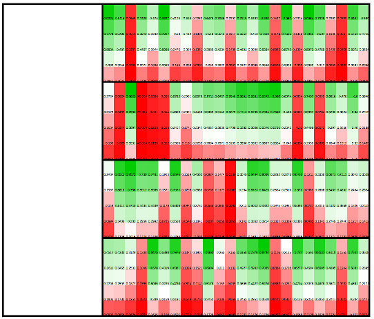
Seems like a layout that reflects the way the battery is physically arranged would be neat. From the little info I have that would be 4 rows of 24 or 28 columns. There's enough pixels to do it even with borders and maybe 5 levels in each cell.

pAupT2H.jpg

The left side would have titles, color legend and a button that changed the display to show each cells voltage, SOC, % of new SOC, or whatever with some kind of vertical scale with colors. You could get a better idea if some area of the pack was experiencing difficulty.

Could also use the same arrangement except change the borders to group the cells together by temp sensor location with temp scale.
 
Cool stuff, guys!

Yeah, this project has taken a bit of a back burner position lately due to other hobbies cropping up, you know how it goes. Haven't given up though :)
 
GeekEV said:
Check out the pending myEV product from myCarma:

http://www.mycarma.com/products/myev/

Thanks, this looks quite interesting. I signed up on their list.

I'll post more info on the design I made, I haven't had a chance to really work on it lately so might as well post what I have (code, schematics, etc) in case anyone else wants to play around with it.
 
As promised, here is where I left off. At its core, you need a Teensy 3.x connected to an MCP2551 (or similar) CAN transceiver and an ILI9341 320x240 display ($8 at PJRC, $4.42 at AliExpress), and a 12v->5v power supply.

Here's my PCB design. Note, the 12v to 5v switching supply doesn't work, I need to get around to bypassing it so I can continue testing. Ignore all of the SWCAN stuff.

https://www.dropbox.com/s/ez1dqaxg4ujnhgs/sparky.pdf

Here's the Arduino-environment source code for the graphical display of the cell voltages. The code is really crude; I'm not proud of it and it could use a lot of improvement, but it does show a way of querying the voltages using DynamicallyDefineMessage that prevents us from overloading/spamming the CAN bus:

https://www.dropbox.com/s/5zjgrh7vuyql20q/sparky2.ino

I still intend to return to this project, someday, but if anyone else wants to take a stab at it, please do :)
 
solder
Think I may have found an error toward the end of the voltages.
Code:
481  define_dpid(0x7e7, 0xfe, 0x0x424a, 0x424b, 0x424c);//was define_dpid(0x7e7, 0xfe, 0x423b, 0x423c, 0x423d);
482  define_dpid(0x7e7, 0xfd, 424d, 0x424e, 0x424f);//was define_dpid(0x7e7, 0xfd, 0x423e, 0x423f, 0x4240);
483  define_dpid(0x7e7, 0xfc, 0x4250, 0x40d3, 0x40d4);//was define_dpid(0x7e7, 0xfc, 0x40d3, 0x40d4, 0x41a5);
Lines 481 and 482 were exact copies of lines 441 and 442, so cell voltages 105,106,107 were same as 90,91,92.
The 0x40d3, 0x40d4, battery_voltage and battery_resistance also get written over in later code
 
Finally got my Arduino due to do some CAN. Here's some output from solder's code on a 2014 Spark:
Code:
 Cell 1:   3.32 Cell 2:   3.32 Cell 3:   3.32 Cell 4:   3.32 Cell 5:   3.32 Cell 6:   3.32 Cell 7:   3.32 Cell 8:   3.32
 Cell 9:   3.32 Cell 10:  3.32 Cell 11:  3.32 Cell 12:  3.32 Cell 13:  3.32 Cell 14:  3.32 Cell 15:  3.32 Cell 16:  3.32
 Cell 17:  3.32 Cell 18:  3.32 Cell 19:  3.32 Cell 20:  3.32 Cell 21:  3.32 Cell 22:  3.32 Cell 23:  3.32 Cell 24:  3.32
 Cell 25:  3.32 Cell 26:  3.32 Cell 27:  3.33 Cell 28:  3.32 Cell 29:  3.32 Cell 30:  3.32 Cell 31:  3.33 Cell 32:  3.32
 Cell 33:  3.32 Cell 34:  3.32 Cell 35:  3.32 Cell 36:  3.32 Cell 37:  3.33 Cell 38:  3.32 Cell 39:  3.32 Cell 40:  3.32
 Cell 41:  3.33 Cell 42:  3.32 Cell 43:  3.21 Cell 44:  3.38 Cell 45:  3.32 Cell 46:  3.32 Cell 47:  3.32 Cell 48:  3.32
 Cell 49:  3.32 Cell 50:  3.32 Cell 51:  3.32 Cell 52:  3.32 Cell 53:  3.32 Cell 54:  3.32 Cell 55:  3.32 Cell 56:  3.32
 Cell 57:  3.32 Cell 58:  3.32 Cell 59:  3.32 Cell 60:  3.32 Cell 61:  3.32 Cell 62:  3.32 Cell 63:  3.32 Cell 64:  3.32
 Cell 65:  3.32 Cell 66:  3.32 Cell 67:  3.32 Cell 68:  3.32 Cell 69:  3.32 Cell 70:  3.32 Cell 71:  3.32 Cell 72:  3.32
 Cell 73:  3.32 Cell 74:  3.32 Cell 75:  3.32 Cell 76:  3.32 Cell 77:  3.33 Cell 78:  3.32 Cell 79:  3.32 Cell 80:  3.32
 Cell 81:  3.32 Cell 82:  3.32 Cell 83:  3.33 Cell 84:  3.32 Cell 85:  3.32 Cell 86:  3.32 Cell 87:  3.32 Cell 88:  3.32
 Cell 89:  3.33 Cell 90:  3.32 Cell 91:  3.33 Cell 92:  3.32 Cell 93:  3.33 Cell 94:  3.32 Cell 95:  3.32 Cell 96:  3.32
 Cell 97:  3.33 Cell 98:  3.32 Cell 99:  3.32 Cell 100: 3.32 Cell 101: 3.32 Cell 102: 3.32 Cell 103: 3.32 Cell 104: 3.32
 Cell 105: 3.32 Cell 106: 3.32 Cell 107: 3.32 Cell 108: 3.32 Cell 109: 3.32 Cell 110: 3.32 Cell 111: 3.32 Cell 112: 3.33
Battery voltage: 372.32 V    (@  0x432D )
Battery SOC: 75.95 %          (@ 0x43AF )
Battery resistance: 0.02      (@ 0x40E9 )
Average voltage: 140.72    (@ 0x41c4 )
Battery current: 3.33        (@ 0x4356 )
As solder noted, the locations may be a little different than the 2015. The last 3 values are incorrect locations or conversions. The rest look good.
The 'Battery current' is ~3.3 with ignition on, drops to 0.0 with ignition off and then to .01 or .02 for any amount of regen. The resistance and average voltage don't change much.
 
Back
Top