Back up camera?

Chevy Spark EV Forum

Help Support Chevy Spark EV Forum:

This site may earn a commission from merchant affiliate links, including eBay, Amazon, and others.
It's stalled out a bit, but I haven't given up. Here's where we stand:

(Nashco is testing out a different approach; I'm only speaking for my own testing.)

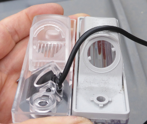
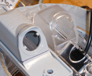
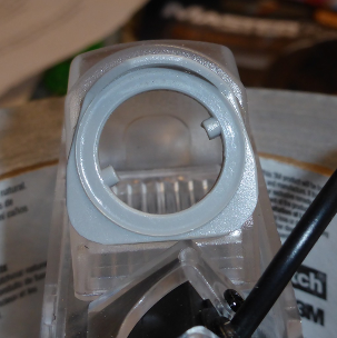
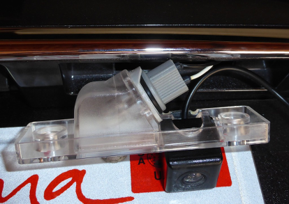
I've found a cheap Chinese backup camera from a Spark that looks like it should fit. You'd have to run wires from the back of the car all the way to the front of the car, to the back of the head unit. You then have to crimp 2 female connectors onto the composite signals from the camera and insert them into the main connector on the back of the radio.

Once you've done that, if you can find a way to coax the radio into displaying the signal, it will display the signal. There are at least 3 approaches I can think of to do so:

  • Reflash the radio with the configuration from a Korean Spark EV. We need a Korean VIN for this, and it's possible this may have other strange effects (change language to Korean? dunno)
  • Modify the existing firmware to enable the camera feature. This was my preferred approach, but I've stalled out here ... It looks like the firmware is updated with a USB key, and I got ahold of the USB key but was unable to decrypt the firmware to even think about modifying it. It might be possible to use something like JTAG? Suggestions welcome.
  • The fallback option is an automated version of what I'm already doing. I can send some diagnostic commands over the CAN bus on the OBD2 connector that "force" the camera to display (for as long as I continue to send the commands). To mimic normal operation, we would need to detect the vehicle shifting into reverse (probably can see this over CAN), and start sending diagnostic commands. Once we detect the car shifting out of reverse, we would stop sending the commands. (To be clear, this would require plugging some -- probably custom -- hardware into the OBD2 port.)

I'll probably work on #3. I can provide info on the necessary CAN messages if anyone else wants to play.
 
solder said:
  • Reflash the radio with the configuration from a Korean Spark EV. We need a Korean VIN for this, and it's possible this may have other strange effects (change language to Korean? dunno)


  • In case it isn't clear, I don't propose installing ALL of the radio software from a Korean spec. As I posted on the top of page 2, there is a calibration specifically for the rear view camera:

    If you go to this website, you can see all of the calibration numbers for different parts of your car (kind of neat to see what could be reprogrammed in there):

    https://tis2web.service.gm.com/tis2web

    Important to note:

    95300891 - Rear View Camera Calibration

    Some gas Sparks in the US accidentally received a "with camera option" rear view camera calibration and threw error messages when there was no camera detected, but unfortunately they were all "fixed" by the dealer without anybody recording the "with camera option" calibration feature. If we can get this calibration for the "with camera option" I wouldn't expect this to change any other functions (such as language, other software features, etc.).

    [*]The fallback option is an automated version of what I'm already doing. I can send some diagnostic commands over the CAN bus on the OBD2 connector that "force" the camera to display (for as long as I continue to send the commands). To mimic normal operation, we would need to detect the vehicle shifting into reverse (probably can see this over CAN), and start sending diagnostic commands. Once we detect the car shifting out of reverse, we would stop sending the commands. (To be clear, this would require plugging some -- probably custom -- hardware into the OBD2 port.)
I'll probably work on #3. I can provide info on the necessary CAN messages if anyone else wants to play.

I am pretty sure I figured out the CAN ID for shifter position if you want to try this approach next, let me know and I'll check my notes. I have the hardware to try this approach out, but frankly tinkering with this is way down on my life priorities right now, so I didn't plan to try that approach myself just yet. First things first, I need to get my hands on a service tool to test and confirm my GM camera is installed correctly.

Bryce
 
Hey solder, do you live in so-cal? I have a friend who's very good at making up CAN boards to do stuff like this for the RAV4 EV (JdeMO) and my leaf (second charger controlled via CAN). Is this the command you're sending on the slow speed single ended CAN or is it the high speed chassis one? If the shift position on the same bus as where you need to send commands, it's a slam dunk.
 
Unfortunately, I'm in NorCal. The commands are "fairly" simple and everything is on the same primary high-speed bus, yes.

(Some understanding of GMW3110 will help the rest make sense...)

You have to start sending TesterPresent commands once a second to the BCM and the Radio. You can then send a DeviceControl to the radio and another to the BCM to turn on the rear camera display. If you want to turn it back off, it should be sufficient to stop sending TesterPresent for 2 seconds, or there's another set of DeviceControls you can send to release control of the system. Here:

Turn on:
Code:
>USDT 241(BCM  (q)) 01 3E 00 00 00 00 00 00 	DIAG (3E) TesterPresent
<USDT 641(BCM  (r)) 01 7E 02 92 02 0F 00 43 	DIAG (7E) TesterPresentPositiveResponse
>USDT 244(Radio(q)) 01 3E 00 00 00 00 00 00 	DIAG (3E) TesterPresent
<USDT 644(Radio(r)) 01 7E AA AA AA AA AA AA 	DIAG (7E) TesterPresentPositiveResponse
>USDT 244(Radio(q)) 07 AE 05 20 20 00 00 00 	DIAG (AE) DeviceControl(05)=[2020000000]
<USDT 644(Radio(r)) 02 EE 05 AA AA AA AA AA 	DIAG (EE) DeviceControlResponse(05)
>USDT 241(BCM  (q)) 07 AE 02 00 00 08 08 00 	DIAG (AE) DeviceControl(02)=[0000080800]
<USDT 641(BCM  (r)) 02 EE 02 92 02 0F 00 43 	DIAG (EE) DeviceControlResponse(02)
[...]
>USDT 244(Radio(q)) 01 3E 00 00 00 00 00 00 	DIAG (3E) TesterPresent
<USDT 644(Radio(r)) 01 7E AA AA AA AA AA AA 	DIAG (7E) TesterPresentPositiveResponse
>USDT 241(BCM  (q)) 01 3E 00 00 00 00 00 00 	DIAG (3E) TesterPresent
<USDT 641(BCM  (r)) 01 7E 02 92 02 0F 00 43 	DIAG (7E) TesterPresentPositiveResponse

To release control:
Code:
>USDT 241(BCM  (q)) 07 AE 02 00 00 08 00 00 	DIAG (AE) DeviceControl(02)=[0000080000]
<USDT 641(BCM  (r)) 02 EE 02 92 02 0F 00 43 	DIAG (EE) DeviceControlResponse(02)
>USDT 244(Radio(q)) 07 AE 05 20 00 00 00 00 	DIAG (AE) DeviceControl(05)=[2000000000]
<USDT 644(Radio(r)) 02 EE 05 AA AA AA AA AA 	DIAG (EE) DeviceControlResponse(05)
>USDT 244(Radio(q)) 02 AE 00 00 00 00 00 00 	DIAG (AE) DeviceControl(00)=[]
<USDT 644(Radio(r)) 02 EE 00 AA AA AA AA AA 	DIAG (EE) DeviceControlResponse(00)

As for detecting the shift into reverse, https://github.com/openvehicles/Open-Vehicle-Monitoring-System/blob/master/vehicle/Car%20Module/VoltAmpera/voltampera_canbusnotes.txt lists two messages which both seem to work (and both are on the same primary 500KHz bus)

Code:
	ID=135	B1	Drive position 0=park, 1=neutral, 2=drive/L, 3=reverse
	ID=1F5	B4	Shift position PRNDL 1=park, 2=reverse, ?=neutral, ?=drive, ?=low

The 1F5 message occurs more quickly and would therefore have less lag.

So, as you can see, it's just a matter of a bit of coding ... for someone ... to make it work. :) If nobody else does, I'll probably end up prototyping it with my current overkill hardware setup and then try to port it to something cheaper and lower-power.
 
Well, that was a frustrating waste of several hours.

I'm collecting data on all 3 busses on the OBD2 connector, and my protocol interpreter doesn't distinguish which bus the message came from. Therefore, I was trying to send messages on the high-speed (500Kbps) bus, and they were being rejected:
Code:
USDT 244(Radio(q)) 07 AE 05 20 20 00 00 00 	DIAG (AE) DeviceControl(05)=[2020000000]
USDT 644(Radio(r)) 03 7F AE 31 AA AA AA AA 	DIAG (7F) NegativeResponse(AE)=31
It turns out, you need to send this message on the 33Kbps SWCAN / "Low-speed GMLAN" bus. The upshot is, you only need that one command to turn the display on, and the TesterPresent command to keep the display on. I've successfully sent those two commands and kept the display on as long as I want.
Code:
>USDT 244(Radio(q)) 07 AE 05 20 20 00 00 00    DIAG (AE) DeviceControl(05)=[2020000000]
<USDT 644(Radio(r)) 02 EE 05 AA AA AA AA AA    DIAG (EE) DeviceControlResponse(05)
>USDT 244(Radio(q)) 01 3E 00 00 00 00 00 00    DIAG (3E) TesterPresent
<USDT 644(Radio(r)) 01 7E AA AA AA AA AA AA    DIAG (7E) TesterPresentPositiveResponse
[...]
The downside is, the reverse signal I was using as a trigger is on a different bus (the 500Kbps primary bus), and the Teensy 3.1 I'm using only has one CAN transceiver (oh, and their FlexCAN library doesn't technically support 33Kbps). So, if I can make the library work, and can find a reverse signal message on the SWCAN, then I can still do this.

I found what appears to be one -- first byte of 102ce040 -- but it's even laggier.

There goes my dream of making a combo reverse-camera enabler and battery monitor -- the latter requires access to the high-speed bus. I could always use two Teensy 3.1's ... they're cheap :/
 
solder said:
Well, that was a frustrating waste of several hours

Nah! All in good fun. CAN reverse engineering takes a long, tedious time. You have helped make the path for others to follow. :) I was wondering about what you said that the radio was on the high speed CAN bus. It seems like in most GM cars it's always on the slow speed bus and it looks like there's no exception for the spark EV after all.

As far as having dual microcontrollers, that's not too big of a deal, just have one dedicated to the single ended CAN and the other (master?) dedicated to the fast CAN. You can link them together with SPI or I2C or even just a logic line (if all you're doing with the single ended side is is sending the screen change commands).

I'm not too familiar with single ended CAN, how are the transceivers wired? Is there a primer out there? I googled a bit but came up dry.
 
JeremyW said:
solder said:
Well, that was a frustrating waste of several hours
Nah! All in good fun.
:) I suppose so, but there's always a moment of frustration when you realize you are barking up the wrong tree!

JeremyW said:
As far as having dual microcontrollers, that's not too big of a deal, just have one dedicated to the single ended CAN and the other (master?) dedicated to the fast CAN. You can link them together with SPI or I2C or even just a logic line (if all you're doing with the single ended side is is sending the screen change commands).
Sure, or I could even wire up an external CAN controller (like the MCP2515) to do the job; there's plenty of Arduino code out there that should work more or less unmodified on the Teensy 3.1 I'm using.

JeremyW said:
I'm not too familiar with single ended CAN, how are the transceivers wired? Is there a primer out there? I googled a bit but came up dry.
Oh, here's where it gets fun! :twisted:
Much of the stuff online says you can get away taking a differential CAN transceiver, wiring CANH to the SWCAN wire, and wiring CANL to ground. This does, in fact, work (on my Beaglebone, not my Teensy), and I'm even (apparently) able to transmit with it. However -- I also get occasional, transient errors ("Service Airbags", "Service TPMS", etc). They go away immediately and don't seem to do any harm, but I don't think I'd be comfortable with that setup while the vehicle was moving.

The proper solution is to use one of a number of SWCAN transceivers -- I have an NCV7536 which should do the job, but it doesn't come in DIP, so I have to make a PCB for it, etc ... Once I do so, if I can modify the divisors in the Teensy code to support 33Kbps operation, then we can test to see how bad the lag is and whether we actually need to look at 2 busses.
 
solder said:
The proper solution is to use one of a number of SWCAN transceivers -- I have an NCV7536 which should do the job, but it doesn't come in DIP, so I have to make a PCB for it, etc ...

Heh tell me about it. Once you go to the CAN/industrial/automotive side, there are no DIP parts practically anywhere. It's all about expensive demo boards and short run prototypes. Can be challenging for the hobbyist. I *do* know eagle CAD and wouldn't mind whipping up a breakout PCB for you in a few days and sending it to oshpark if that would help.

Any particular reason you are married to the Tiny? I'm familiar with the AT90CAN128 which is a pretty cheap chip and can be used with the arduino ecosystem and has a built in CAN controller (like the Tiny 3.0). I need to figure out if that CAN library supports the slow speed baud rate. There's also the MBED which has dual CAN controllers but it's a $50 part...

Sounds like the differential CAN transceiver hack has issues detecting collisions or the bus is easily saturated. Keep in mind that a lot of airbag and related safety features probably have a certain timing about their messages (the leaf is like this) and if you collide with their packets you're going to see stuff like this that is hopefully self healing. Normally the recessive/dominant way of the bits allows for detection of another sender on the bus, but it seems like maybe the hack isn't quite foolproof when it comes to collision detection (or is this feature only on differential CAN?!). Also note that this bus is an order of magnitude slower than the high speed bus, so it's probably easily saturated, although you're not exactly bombarding things with a single message. :)

I don't even own a spark yet but I really want a back up camera when I do get mine!!! :lol: Probably going to pick mine up in July.
 
JeremyW said:
solder said:
The proper solution is to use one of a number of SWCAN transceivers -- I have an NCV7536 which should do the job, but it doesn't come in DIP, so I have to make a PCB for it, etc ...
Heh tell me about it. Once you go to the CAN/industrial/automotive side, there are no DIP parts practically anywhere. It's all about expensive demo boards and short run prototypes. Can be challenging for the hobbyist. I *do* know eagle CAD and wouldn't mind whipping up a breakout PCB for you in a few days and sending it to oshpark if that would help.
I appreciate the offer! I was trying to avoid having to wait for the turnaround time to test out the transceiver ... I actually designed a single-sided breakout board in Altium to try to use with a PCB-milling machine but encountered technical difficulties. I'll probably suck it up and send out a board to oshpark tonight. I also have a SOIC breakout board I should be able to use, in a pinch.

JeremyW said:
Any particular reason you are married to the Tiny? I'm familiar with the AT90CAN128 which is a pretty cheap chip and can be used with the arduino ecosystem and has a built in CAN controller (like the Tiny 3.0). I need to figure out if that CAN library supports the slow speed baud rate. There's also the MBED which has dual CAN controllers but it's a $50 part...
Mostly the small, easy-to-use form factor and the fact that I have several of them; I also like the speed. (I'm planning on using one for a battery-health-monitoring gadget I mentioned in another thread). It is, admittedly, overkill for this application ... I do think that I can get its FlexCAN driver to support 33Kbps (see https://github.com/teachop/FlexCAN_Library/blob/master/FlexCAN.cpp#L42 ; I think we just need an entry with FLEXCAN_CTRL_PRESDIV(29) for 33333 bps).

I actually have an mBed I could try, but it's so old that it's no longer supported by their online IDE and you have to use the offline toolchain to get it to work... at that point, the Teensy is easier to use.

JeremyW said:
Sounds like the differential CAN transceiver hack has issues detecting collisions or the bus is easily saturated. Keep in mind that a lot of airbag and related safety features probably have a certain timing about their messages (the leaf is like this) and if you collide with their packets you're going to see stuff like this that is hopefully self healing. Normally the recessive/dominant way of the bits allows for detection of another sender on the bus, but it seems like maybe the hack isn't quite foolproof when it comes to collision detection (or is this feature only on differential CAN?!). Also note that this bus is an order of magnitude slower than the high speed bus, so it's probably easily saturated, although you're not exactly bombarding things with a single message. :)
Nah, I get these blips when I'm not transmitting anything -- not a collision issue or saturation issue. It's a signal-integrity issue, and I'm surprised it works at all. I expect it to go away once I'm using a transceiver that was designed for the application.

JeremyW said:
I don't even own a spark yet but I really want a back up camera when I do get mine!!! :lol: Probably going to pick mine up in July.
You'll love it, they're great cars and you can't beat the performance for the price. Plus, it's cheap enough that I don't feel too guilty taking the thing apart ;)
 
Hello,

Once again big respect for your work solder.

I have provided one of my HappyTV modules to Nashco. Unfortunatly he has somekind of a problem.
He first had a problem with a aftermarket camera (chinese i think, that came defect) and then opted for the original backup camera (which has 6 wires, that i dont natively support), but he didnt get it working. We try to sort it out.

I have a working plug and play module that runs in your sparks (and also on the sonic and others), providing a rear view camera and another video/audio input.
The only thing is, that i dont have a sales man in the states at the moment.

If you want one, i can provide you with it from Germany.
PM me for the manual (that i am just translating into English)

As solder wrote, it was not that easy to have it make the job(CAN Mirroring), but now we have sold around 50 units here in Europe and they work fine.

Bernd
 
CANtronix said:
I have provided one of my HappyTV modules to Nashco. Unfortunatly he has somekind of a problem.
He first had a problem with a aftermarket camera (chinese i think, that came defect) and then opted for the original backup camera (which has 6 wires, that i dont natively support), but he didnt get it working. We try to sort it out.

We have been communicating via email, and honestly I haven't had updates for quite a while because I've had little time and several failed attempts. I've had two bad cameras, it seems. The first one was the one Bernd recommended I buy (from ebay), but it had a problem with image quality. The second one was a GM camera made specifically for the Spark, but it doesn't work AT ALL (just black screen) and I don't know if it is a bad camera or I'm doing it wrong. I am trying to use a service tool to test it, but my service tool has also been quite difficult. I now have a third camera to test (same one as solder is testing with), but haven't had time to install it yet.

So far in my testing with the HappyTV, I don't think it works the same for the Spark EV as it did for the Opel Adam that Bernd has been using. I just received the first draft of English instructions, so hopefully I can provide some useful feedback in the coming weeks and clarify how it does work with the Spark EV.

I said way back in this thread that I can see an image, and so has solder, so we know it's possible. Now it's just a matter of seeing an image PROPERLY that is the trick (shift to reverse, see a clear image of the area behind the car), and nobody has done it with the Spark EV yet. Close, but no cigar.

Bryce
 
The HappyTV looks like quite a nice device, I hope we can get it working with our cars!

Meanwhile, I'm over-engineering the backup-camera solution by folding it in with a battery monitoring device, see http://www.mychevysparkev.com/forum/viewtopic.php?f=10&t=4166

I mean, if I'm going to make a board to do SWCAN, I might as well go all the way ... the LCD is only $5-$8... ;)
 
Solder - really exciting news. Hope to see the backup camera work with the Spark EV work some day.... sooner preferable ;)

Regarding the new board you're working on, if you have an additional LCD, why not just use it for backup camera, or EVEN BETTER, if you manage to access the Spark EV display, why not use it to display the data? why have an additional display, the clutter and extra cost?
 
Hi guys,

Nice work solder, if you need anything, i can provide you the information (Also my SWCan layout if you need).

@ Nashco

You had it bad with the first camera. The original Rearview cam to my information uses a special GVIF video input only for this (Blue Connector). Not every Mylink has this option installed (You may see it in the back, when you have it out of the car) So even programming this option wont work on a lot of cars.
I recommend you buying another camera and it will work, or you try to rewire the original cam. I just found this:

http://gm-volt.com/forum/showthread.php?81874-How-To-Add-A-Backup-Camera-To-Your-OEM-Radio-W-Pictures
There you can find the 6 wire camera connector.

I am 100% sure the HappyTV works in the Spark.

Bernd
 
For those following along, the HappyTV is still not confirmed to work properly in the Spark EV. I did finally get a camera that works properly (thanks solder, I owe you!)...but the HappyTV isn't work like Bernd says it should, so we have to do some further investigation.

I swear, this car will eventually have a rear view camera display even if it kicks and screams the whole way!

Bryce
 
Here's some pics of installing the camera solder found at: http://www.aliexpress.com/item/hot-...A-AVEO-CRUZE-CAPTIVA-BUICK-GL8/553378821.html

The light bulb holder is not correct.
TsszphH.png


So I propose to cut the original on the black line
1rK53dM.png


and glue the piece onto the new camera-bulb holder like so.
MvDczNr.png


Seems to work ok !
Yjmlgnl.png
 
bicycleguy said:
Here's some pics of installing the camera solder found at: http://www.aliexpress.com/item/hot-...A-AVEO-CRUZE-CAPTIVA-BUICK-GL8/553378821.html

The light bulb holder is not correct.
TsszphH.png


So I propose to cut the original on the black line
1rK53dM.png


and glue the piece onto the new camera-bulb holder like so.
MvDczNr.png


Seems to work ok !
Yjmlgnl.png
Okay, I need to get off my ass and do this (the install of the camera), because I think I know enough to prototype the CAN stuff with hardware I have laying around (rather than trying to debug my custom hardware). Did you run the wire up to the head unit? That seems like it will be annoying.

For posterity, the plan is to watch for this on the SWCAN bus:

1020c040 -- goes from 00 x0 04 04 01 to 00 x0 06 04 01 when car goes into reverse (and goes back to 04 in every other shifter position).

When it shifts to 06, send (on SWCAN)
Code:
>USDT 244(Radio(q)) 07 AE 05 20 20 00 00 00    DIAG (AE) DeviceControl(05)=[2020000000]
Then, as long as the car is still in reverse, send this every 1-2 seconds:
Code:
>USDT 244(Radio(q)) 01 3E 00 00 00 00 00 00    DIAG (3E) TesterPresent
Once it shifts back to 04, stop sending TesterPresent and the display will revert to normal within 3 seconds. That's the simplest thing that could possibly work; if it's too laggy, we can send a command to immediately disable the rear camera (see comments earlier in thread).

If that works, then I can make a small piggyback board for the Teensy with a real SWCAN transceiver, which will hopefully be more reliable than the hack I'm currently using with my BeagleBone. (I get random "service airbag" messages, which quickly go away...)
 
Back
Top