Back up camera?

Chevy Spark EV Forum

Help Support Chevy Spark EV Forum:

This site may earn a commission from merchant affiliate links, including eBay, Amazon, and others.
Folks, be careful here. I'm as embarrassed as you are by the fact that our head units really run Windows CE, and there's a lot you can mess up there; At least a few Russians have bricked their head units after I releasted the Developer Mode pw. I feel really bad about that, please be careful; I've hacked other head units before and had great succeess, though I never ended up with a truly safe solution like I have in previous endeavours.

GTPprix is clearly a talented reverse-engineer, well-versed in the ways of IDA Pro (and then some). I'm sure he offers a fine service and it seems to put a roof over his head. Good for him. I have an unrelated day job and I'm motivated more for the fun of it and enjoy sharing my work with other people, but to each his own. I've bought a few junkyard-car head units -- no, they don't work in the car due to antitheft, but I'm working on that -- and I'll try to keep you guys posted on what I learn, because that's the way I like to work.

Cheers to all,
-solder
 
I finally got around to working on this again. I've mounted the camera and routed the camera wires to the back of my 2014 Spark head unit. Routing through the rubber accordion between the rear door and body was the funnest. I could only find an incomplete link on the wiring.
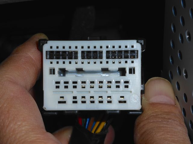
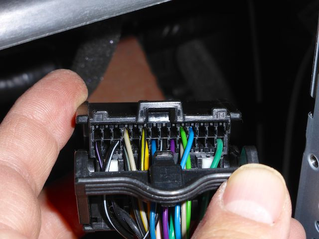
I need the following pin numbers:

video input
ground
12V
SWCan

and maybe:
video ground?
SWCan ground?

I think all the signals can be had on this connector.
3FnW0jk.jpg
mAv739U.jpg


I plan on clipping onto existing wires where possible and finding contacts somewhere for the rest. Any idea on which cars I can cannibalize contacts from? Haven't been to a junkyard in years. Doubt they have any Sparks. Can I get these from the dealer?

thanks
 
You can buy the contacts from Mouser, http://www.mouser.com/ProductDetail/JST-Automotive/SAIT-A03T-M064/?qs=XoGB3caz5%2FYuMOQxroGfSw%3D%3D

Video input +: pin 7
Video input -: pin 8
SWCAN: pin 28
Signal ground: pins 17, 22
Ground: pin 38
+12V: pin 44

Have any tips and tricks for routing the wiring? I got stuck on that pretty quickly....
 
I installed the GM Spark rear camera kit, which included a new harness to run from the head unit to the rear hatch. It was a real PITA and took way longer than I thought! I also learned that the GM harness going from the rear hatch hinge to the rear license plate area routes inside the hatch around the glass, which makes perfect sense. What doesn't make perfect sense is that there is a single wire harness clipping point that you can't get to unless you remove the rear glass, which is glued in, of course. Ultimately, I was able to remove my old harness and install the new one with the kit with a LOT of effort. I had to de-pin one of the larger connector bodies IIRC to get it installed without removing the rear glass.

If I were to do it again, I would definitely not do it the way I did it the first time. It would probably be much easier to get some multi-conductor wire that is appropriately small gage and route this along the stock harness and terminate the wires afterwards. If I ever try this again and figure out a decent way, I'll try to put together a tutorial because it's a real PITA the way GM designed the hatch harness and glass.

Bryce
 
solder,
Thanks for the quick reply. My best tip might be hard to come by. Found it in my garage. I used 3ft long .065dia. aluminum welding rod to probe possible
routes and then pull the wire through. This wire is really soft so it won't scratch paint or insulation. It is stiff enough that you can jam it forward and it will arch around obstacles ect. You can bend the end in such a way that when you rotate the other end it will swing around hopefully past the hole your trying to get to next. Once you get it to the next opening you can either hook the end to pull a loop of string back out or tape string to it to pull through.

Roughly I did this:
1. Pulled off little ~3X3 panel in driver side of lift gate.
2. Bent aluminum wire in kind of a big arch, taped string to front and shoved in camera-license light hole.
3. Looking through panel hole, hooked the string with another aluminum wire.
4. Pulled string, then camera wire with RCA plug through.
5. Connected the 12V and video wire to the special power RCA wire that came with the camera. Wrapped the connector in foam and tape so it won't rattle and tie wrapped next to the panel opening.
6. Cut off the RCA connector at the other end of the special wire because it will need different termination anyway and gets caught on everything.
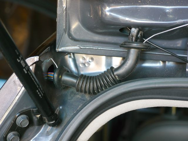
7. Pulled accordion rubber thingy out of lift gate and slid to left as far as possible.
8. Pushed aluminum wire up along glass to hole above. At first I though coming out near the glass might help but abandoned that and went all the way to the accordion hole. Pulled string back, taped to wire and pulled wire through. Seemed like this would be impossible, but I managed to do it twice as the string came off once. If you bend the aluminum slightly in the right directions it's actually pretty easy.

Next.. Tricky part next.
 
solder,
Is the Video input -:pin 8 just ground?

There are only 3 wires on the camera wire harness 12V, video and ground. Did you use that for ground of one of the other grounds?

Mike
 
bicycleguy said:
solder,
Is the Video input -:pin 8 just ground?

There are only 3 wires on the camera wire harness 12V, video and ground. Did you use that for ground of one of the other grounds?

Mike

I think my camera had a separate video -, but connecting pin 8 to ground *should* work.
 
Here's the part I had the most fun with:

YHqxLwt.jpg

You can see the black video/power wire coming out of the hole sloping downward to the right at an angle. The aluminum welding rod guide wire is shoved through the accordion and about an inch out the left side. This was relatively easy to do. The hard part was that I couldn't seem to pull a string or later the video wire through. The string or wire kept breaking or detaching.

Turns out you have to be very careful to keep the guide wire all the way to one side and not let it mingle through any of the wire bundle. If you do the wire will get grabbed by the wire bundle, kind of like a Chinese finger trap toy. The more you try to straighten it out or pull, the harder it grips.

Talcum or baby powder dumped liberally will help tremendously but you must avoid looping the guide wire through the bundle wires.
 
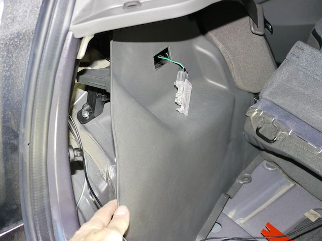
The rest was easy, but a little scary as your pulling apart the interior of your new car. :( Unclip the bottom and pull out the quarter panel a little. You don't need to remove it.

wIftOse.jpg

I was able to just shove the video cable into the top accordion quarter panel hole and it started showing up as seen in the picture above by my finger.

cqdVeys.jpg

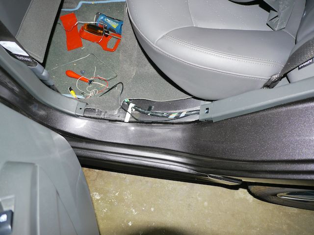
After pulling off the trim pieces routing the rest of the way is straight forward.
 
Reviewing my pictures above reminds me of a question I had. In the quarter panel picture if you look carefully where the folded rear seat back meets the wheel well you can see a little spring pin hinge thingy. If you fold the seat forward this device allows the bottom of the seat back to move up or down about 2 1/2 inches. I figured it must be some sort of seat-back release but couldn't figure out how it works. You have to give it a little pull to see that it moves. It snaps back into place when you make the seat vertical and push into place.

Maybe the shop manual talks about this or I missed it in the owners manual someplace.

thanks
 
If you compress the spring (push the seat towards the closest door), then that pin can slide up enough to eventually get to the top of the T shaped slot. Once it's out of the T slot, you have to carefully move the upholstered arm rest/air bag cover enough to continue lifting it up until the seat is at enough of an angle to detach the center section. The center of the two seat halves have a male and female pin and socket that go through the center bracket. It took me forever to figure this out (before the service manual was available), but now that I've done it it's a piece of cake. This is a situation where a video would probably be worth a million words...it's pretty obvious once you see it.

Bryce
 
sTeeve said:
Meanwhile, during another lazy Sunday morning tea + YouTube couchsurfing session...

https://navtv.com/products/NTV-KIT626/gm-k-prg.html

299 bones.

There's also a video:

https://www.youtube.com/watch?v=1ui2Tw1WZr0

-Bob K.

Update: I spoke with Jay at NavTV. His service is $299. He said they were "95% sure that it would work on the Spark EV". We arranged for me to purchase the kit; they charged my credit card but no package arrived.

Turned out they are not confident enough yet that the kit will work with the Spark EV; Jay had my package sitting on his desk, but he would not agree to ship it until they could test their kit on a Spark EV (to which they have access, he said, from a car rental place in Miami).

Sooooo.....I'm waiting to hear back from Jay before anything else happens. The refunded my money, so we're back to square one.

Jay's kit is different from Chris' in that he ships hardware to you that you install rather than you ship your head unit out to be reprogrammed. Of course, price is different, too.

Solder et al...keep after it! I really really really want this to succeed. I got spoiled by the rearview cam in my Leaf!

-Bob K.
 
Sure, please don't wait for me, I'm easily distracted :) I'm curious to see how well various approaches work, but I'm still hoping to come out with a free software-only solution. Eventually.
 
sTeeve said:

This looks to be extremely similar to the HappyTV which I tested with Bernd. There were a few kinks that we worked through, and I helped translate an English manual (which I keep forgetting to mail to him). So far, the only remaining issue with the HappyTV is that when it is installed it prevents OnStar monthly diagnostic checks from completing (at all, for any system). If you don't care about the OnStar diagnostic capabilities, then it's not an issue. If you want to keep this functionality, which is included with your Spark EV for at least 5 years for free, perhaps longer depending on your model, then this may be a deal breaker.

The other difficulty with these systems is that they don't include a plug-and-play camera. Having to come up with your own power, ground, camera, etc. leaves several details to iron out which may or may not be correct. Having a plug-and-play setup would seem to add much more value than they would cost, in my opinion.

Bryce
 
solder said:
Sure, please don't wait for me, I'm easily distracted :) I'm curious to see how well various approaches work, but I'm still hoping to come out with a free software-only solution. Eventually.

In that vain...
I'm currently using an Arduino Due with a toggle bit shield that I modified by replacing one of the regular can transceivers with a Freescale MC33897CTEF/R2 SWCAN transceiver. I'm able to read the SW bus:
Code:
ID: 0x10380099 Len: 1 Data: 0x1				Defroster on
ID: 0x10380099 Len: 1 Data: 0x0				Defroster off
ID: 0x102CE040 Len: 8 Data: 0x0 0 22 0 0 0 6 A0  	P or N
ID: 0x102CE040 Len: 8 Data: 0x1 0 22 0 0 0 6 A0  	D or L
ID: 0x102CE040 Len: 8 Data: 0x2 0 22 0 0 0 6 A0  	Reverse
but can't seem to write to it. To send the turn on command, from your previous posts, I'm sending the following:
Code:
void sendCameraON(){
  CAN_FRAME outgoing;
  outgoing.id = 0x244;
  outgoing.extended = false;
  outgoing.length = 7; 
  outgoing.data.s0 = 0xAE05;
  outgoing.data.s1 = 0x2020;
  outgoing.data.s2 = 0x0000;
  outgoing.data.s3 = 0x00;
  setSWCANWakeup();
  Can0.sendFrame(outgoing);
  delay(5);
  setSWCANEnabled();
}
The frame structure is different from the FlexCAN of the Teensy but you probably get the idea. I'm not sure of the terminology you posted:
Code:
 * >USDT 244(Radio(q)) 07 AE 05 20 20 00 00 00    DIAG (AE) DeviceControl(05)=[2020000000]
 * Then, as long as the car is still in reverse, send this every 1-2 seconds:
 * >USDT 244(Radio(q)) 01 3E 00 00 00 00 00 00    DIAG (3E) TesterPresent
I don't know what USDT, Radio(q) and DIAG mean. I'm still trying to figure out how PIDS relate to these CAN frames.
Any elucidation ?

FYI I'm using the circuit on the freescale data sheet for the transceiver and my own mods to due_can and don't have any problems with messing things up receiving. The response to shifting into or out of reverse is immediate, (in human terms). Have started playing with the Teensy 3.2, it's awesome.
 
bicycleguy said:
The frame structure is different from the FlexCAN of the Teensy but you probably get the idea. I'm not sure of the terminology you posted:
Code:
 * >USDT 244(Radio(q)) 07 AE 05 20 20 00 00 00    DIAG (AE) DeviceControl(05)=[2020000000]
 * Then, as long as the car is still in reverse, send this every 1-2 seconds:
 * >USDT 244(Radio(q)) 01 3E 00 00 00 00 00 00    DIAG (3E) TesterPresent
I don't know what USDT, Radio(q) and DIAG mean. I'm still trying to figure out how PIDS relate to these CAN frames.
Any elucidation ?

FYI I'm using the circuit on the freescale data sheet for the transceiver and my own mods to due_can and don't have any problems with messing things up receiving. The response to shifting into or out of reverse is immediate, (in human terms). Have started playing with the Teensy 3.2, it's awesome.

Awesome, I'm glad to have someone else is looking at this. I'd be happy to share my ugly Perl code that I'm using to decode these protocols :)

Sorry for being unclear. The packets that need to be sent are 8 bytes long .

ArbID=0x244, data is 07 AE 05 20 20 00 00 00
ArbID=0x244, data is 01 3E 00 00 00 00 00 00
 
Nashco said:
If you go to this website, you can see all of the calibration numbers for different parts of your car (kind of neat to see what could be reprogrammed in there):

https://tis2web.service.gm.com/tis2web

Important to note:

95300891 - Rear View Camera Calibration

Using this same website for the Canadian unicorn with the rear view camera (KL8CL6S01EC400054) yields this:

95405806 - Rear View Camera Calibration

Exciting! Now, to figure out how to get the radio programming changed...

Bryce
 
I contacted Jay at NAV-TV about this upgrade along with our new information. He says "I was told today we are good to go with the electric versions.".

I'm not ready to pull that trigger just yet. I want to do some more research.

Oh, and that Canadian unicorn doesn't have DCFC:

 
Back
Top